ROLAND FD8 - Hi hat stand Mod for the DIY guys :)

Kit-Toys

UPDATED TO MORE SIMPLE VERSION!!
DIY ....
your on your own with this one ....but here is how to do it :)
 
Its possible to make this by drilling just 5 holes and making a bar with 2 holes in it !
 
how simple does anyone need it to be  :)

MORE STUFF !
 
Ok hi hat controller to hi hat stand  'mod'
quite a few around but i thought they looked quite messy over the top
This is neat and EASY to make.


The mod is as basic as possible using parts from the stand where possible.
This mod is built around a ROLAND FD8 and premier hi hat stand because they are quite common.
 
It needs one extra part making (a bar with 2 holes in it..not rocket science)
 
hardware = 2x 6mm bolts , 1x6mm bolt and nut, 1x4mm bolt and nut + 2 washers...a project box (maplin ect)
 
just need to drill 5 holes in the plate (2 in line with anti creep spikes 6.5 mm)
one in the hi hat front 6mm and two holes to hold on the project box that is 'riveted on 4mm x 8'  ......(but could use 4mm bolts)
 
 
im going to do a break down on how to put this together
but for now a few pics.... built this today !..rush job :P
 
TOP TIP if you have an FD8 and the foot chick and heel splash isnt to good  GREASE the top of the rubber roller where the metal pushes it down..
Works wounders!!


pict0076.jpg

FINAL LINK NOW LIKE THIS >>>>
Take the white wheel off use a long 6mm drum bolt to attach the link bar.
Use a 10mm nut as a spacer at the back ...this way you can adjust the pedal hight  without affecting the control distance.
 

apict0067.jpg

pict0059.jpg

drill out the pin holding the old premier foot plate on.
 
Remove the chain by unscrewing the whole unit (remove the nut that fastens it to the bottom of pull rod)
 
ok the BIG mistake people make when building a stand like this is to put the hi hat controller foot pedal to far away from the stands pul rod.
If the pedal is to far way the cymbal will be out of reach(get the pedal as close as possible to the resistor strip.
Most hi hats have to anti slip thumb screws
(these have a 6mm thread very handy)
 

pict00638.jpg

After the plastic housing is removed the  struts can be a lot  closer to the sensor .The plastic flat cable bends round in to new box...keep the black metal bent plate on the top of the pedal as it normally is...not under like this pic shows

pict0044.jpg

the link ...Strip of metal with two 6mm holes
now 55mm appart approx .....

step one
 
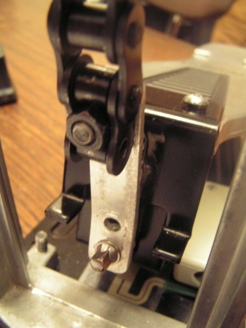
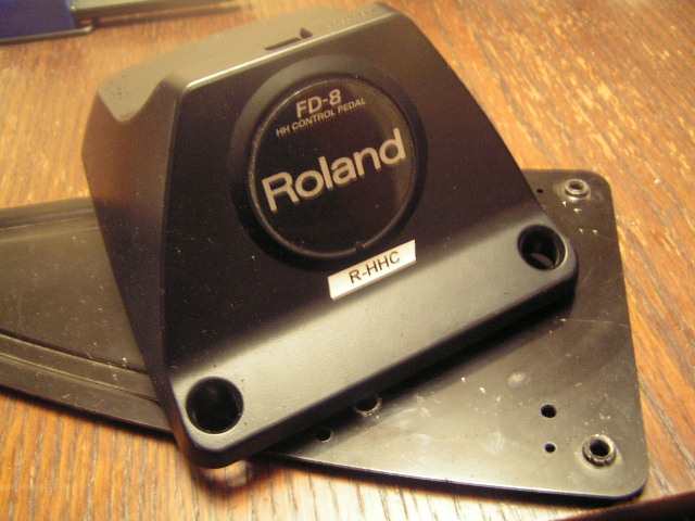
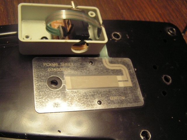
take off roland front box ..... be carful not to damage the ribbon cable.

pict00a05.jpg

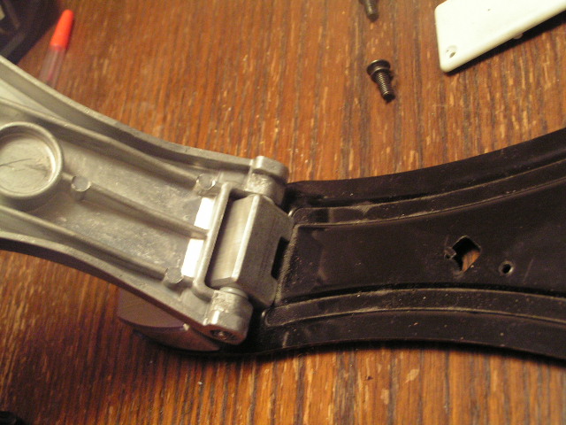
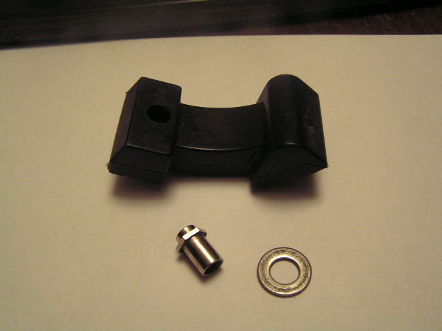
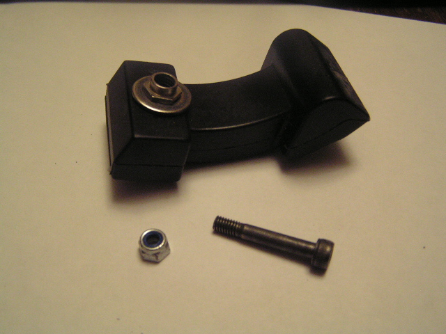
remove heel spring(not needed)

pica009.jpg

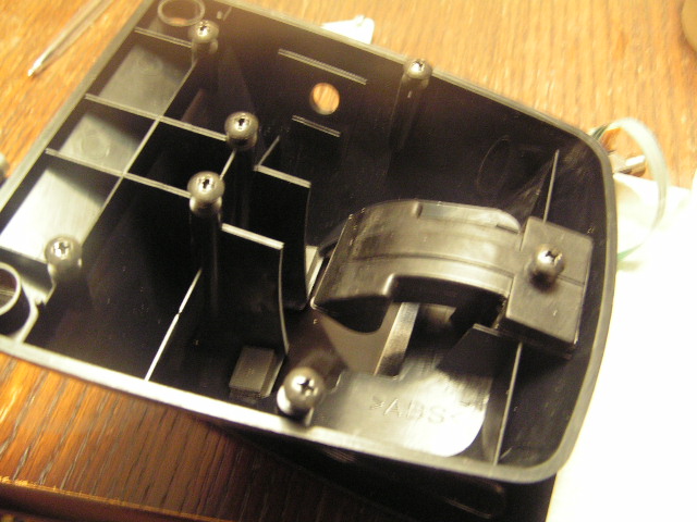
take out rubber foot

pict0a13.jpg

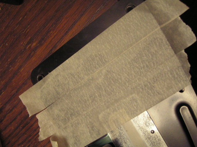
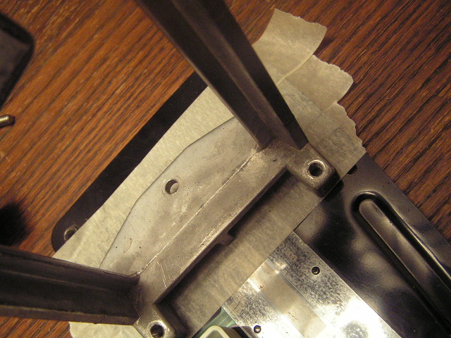
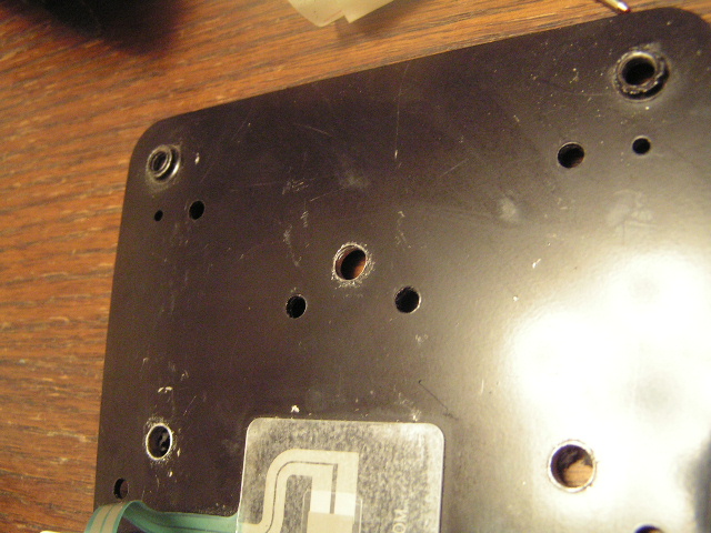
add masking tape to the end of the pedal so you can see the sensor and draw a few
drilling points

pict0a011.jpg

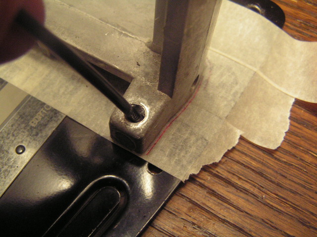
note hole drilled at front for extra grip...use a pen refill to get down in side the holes and mark out hole positions
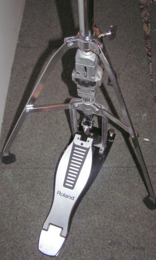
**at this point it is important that the rubber roller foot clears the front of the stand when fully depressed***
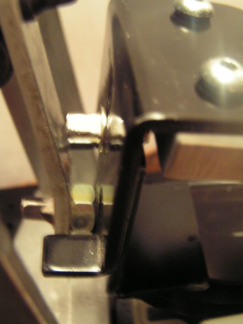
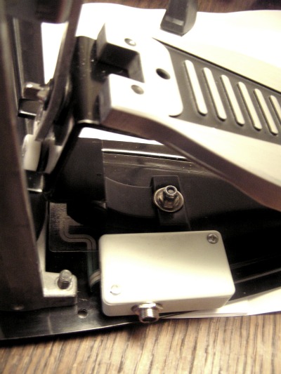
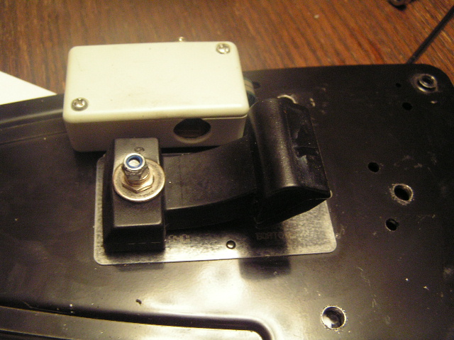
best mount  the project box and jack at this point so not to damage it((note i got the hole in the wrong side oops)((make sure the depressing plate does not hit this box
(the box could even be held on with a double sided tape pads ..but best with rivet or bolts .....?

pict0038.jpg

cable hole has a cut away in it to let the cable pass through

pict0035.jpg

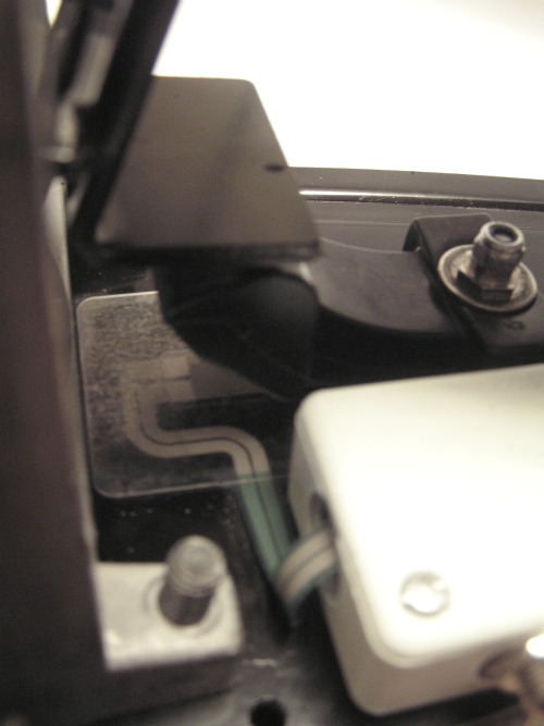
i used a drum lug nut and a washer to fill out this hole in the rubber foot ...
 
The FD normally suffers with dust getting under the foot
this version is easy to clean also to see what is happening while setting up....dont forget to re grease the rubber foot.

pict0029.jpg

pict0031.jpg

remember the rubber foot or black pressure plate must not hit this cross bar

pict0018.jpg

marking with pen re fill ....make these holes 6.5mm or even 7mm..the bolt will be 6mm but will be going in at an angle

pict0020.jpg

pict0022.jpg

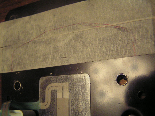
there we have 3 x 6.5mm holes ...the only other holes are 2x 4mm to hold the project box on

pict0024.jpg

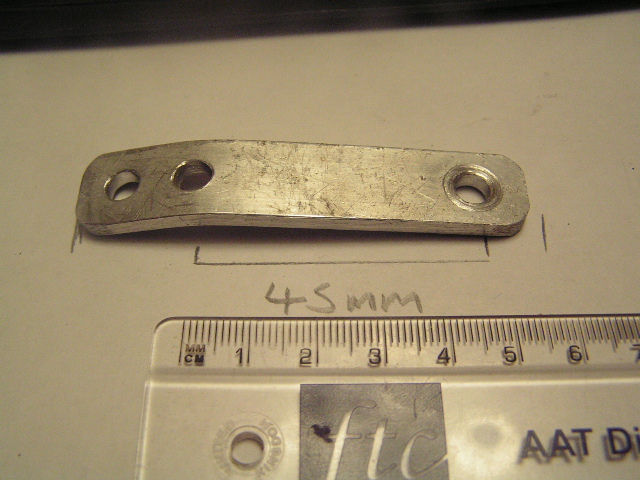
Make a Metal strip ..this is an old bit of alloy, it has 3 holes because i got it wrong frist time :)
 
)but in the end i did use the holes at each end )))
55mm worked for me,again 6 mm holes.
 it will need a bend in it

pict0045.jpg

add your bar  ..notice bolts ready to screw into hi hat stand

pict0052.jpg

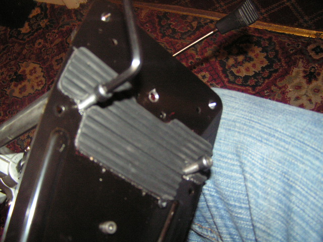
with last bolt and nut added

pict00a54.jpg

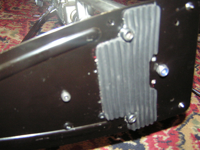
the bottom bolt on the pull rod is the anchor  point of the whole stand make sure its locked down hard to avoid rotation of the pull rod
 
there you have it.... thats as simple as it can be done i recon :)
 
built in A TEAM STYLE
using as little extra bits as possible....all stands are different so use the force luke

Enter content here

there you have it ...hi hat